- Published Feb 2, 2023
- Last Modified Aug 29, 2023
- 9 min
A Guide to Shunt Resistors
Explore how shunt resistors work and find out more about their role in electrical circuits with our handy guide.

What are Shunt Resistors?
A shunt is an electrical device that generates a low-resistance path for an electrical current. This enables the current to flow to an alternative point in the circuit. Shunts may also be referred to as ammeter shunts or current shunt resistors.
Shunt resistors are commonly used to measure high currents, with the low levels of associated resistance. Shunting literally translates as diverting or following a force along a set path.
There are a number of instances in which the measurement of current will be required. Common applications include over-current protection, 4-20mA systems, battery charging, and H-bridge motor control. The application of the Ohm’s law equation allows the level of voltage and current flow to be measured in amperes. This requires the positioning of a resistor in parallel with the ammeter. There is a resulting division of current, enabling the measurement of the amperage level.
Electrical Shunts in Circuits
There are various ways of measuring the electrical current flowing through a circuit. However, the most common method is to make an indirect measurement, identifying the level of voltage across a precision resistor with reference to Ohm’s law. The resulting voltage drop will correspond directly with the current which passes through the circuit. The correct identification of this voltage drop will enable you to gauge the magnitude of the current flow.
A high level of care should be taken over the positioning of the shunt within the circuit. It is usual to place the shunt as close to the ground as possible when there is shared ground between the circuit and the measurement device. This allows for the protection of the ammeter against the common mode voltage, which might otherwise cause damage and misleading results. It will be necessary to isolate the shunt from the ground or incorporate a voltage divider for protection inside the ungrounded leg.
See the diagram below for help identifying the different components of a shunt:
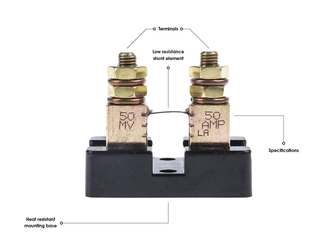
What Does a Shunt Do?
The electrical shunt is a device that enables the current to pass through or be diverted past a set point in the circuit through the creation of a low-resistance path. Some meters feature in-built precision current shunts and allow measurements to be taken in terms of DC current and Watts. There are also electrical shunts that measure the flow of DC current.
The Ohm’s law formula is applied as follows:
V = I × R
This equation is specific to the voltage (V) across the resistance (R in ohms) being generated as a result of the resistance and current (I in amps) circulating through the resistance. As an example, a current shunt with resistance of 0.002 ohms and current of 30 Amps will result in the generation of 0.002 x 30 = 0.06 volts or 60 mV (milliVolts).
You can assess the voltage drop across the shunt by integrating a current shunt within a circuit set up for measurement. The assessment of the current shunt resistance will allow for the calculation of current measurement in accordance with the Ohm’s law calculation. Ohm’s law can also be used in calibration of the current shunt resistance.
Common applications of the shunt resistor include:
- Measurement of current circulating through a battery and monitoring of power generation
- Redirection of high frequency noise (this requires a shunt featuring a capacitator) before the signal reaches circuit elements
- Installation within a DC connect enclosure featuring a negative conductor between the batteries and inverter
- Overload protection in control devices including battery chargers and power supplies
You might use the types of shunts highlighted below:

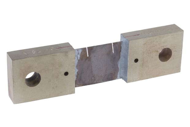
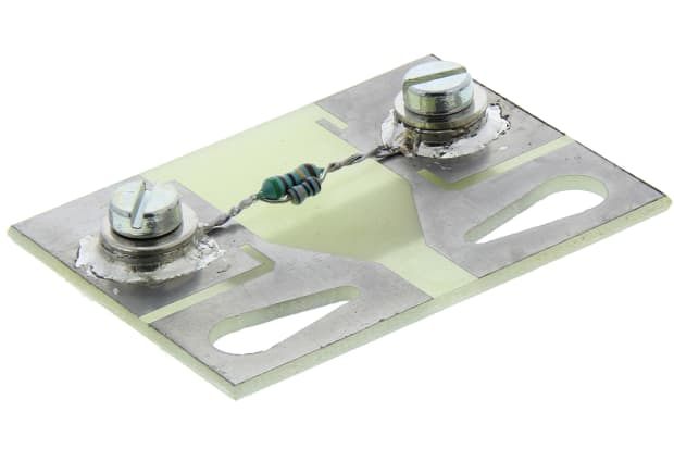
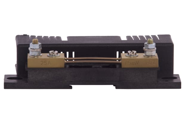
Murata Power Solutions Digital Shunt
Output :
- 50 A
- 50mV
Best for? :
- Measuring dc currents from 5A to 1200A
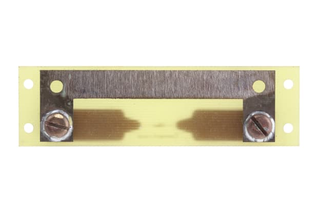
Hobut Shunt
Output :
- 20 A
- 200mV
Best for? :
- Converting digital panel meters with 199.9mV full-scale deflection into ammeters
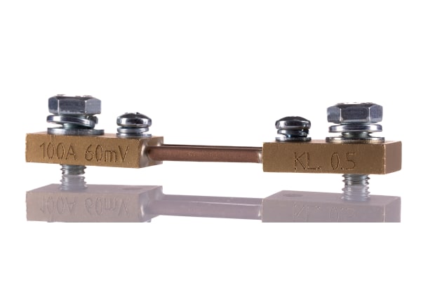
GILGEN Muller & Weigert Plate Shunt
Output :
- 100 A
- 60mV
Best for? :
- Measuring higher currents with DQN moving-coil instruments
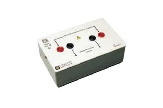
Chauvin Arnoux Plate Shunt
Output :
- 10 A
- 100mV
Best for? :
- Measuring currents up to a rating of 10A with a high level of accuracy
DC Panel Ammeter Shunts
The DC panel ammeter shunt is one of the most commonly used devices of this variety. It allows for the accurate measurement of current values greater than those that could be measured with an ammeter exclusively. This process involves diverting a small amount of current to the meter for measurement.
It is necessary to set the level of resistance so that the corresponding voltage drop can be measured without disrupting the circuit. The level of current has a direct bearing on the voltage that flows to the shunt, enabling the correct current level to be identified.
How Does a Shunt Work?
There is a difference between the technical limitations of the shunt resistor and standard resistor. Shunt resistors allow for high levels of precision, offset against a minimal ohmic value. Kelvin connection is recommended to achieve such high precision. This connection avoids issues such as lead resistance and sensitivity.
There are a variety of reversible and irreversible factors that may have a bearing on the value of a shunt resistor. The associated mechanical, electrical, and thermal loads mean that there is long term stability and irreversible change in resistance. The Temperature Coefficient of Resistance (TCR) is expressed in ppm/oC and corresponds with the drift resulting from the cooling or heating of the transistor due to the fluctuation in ambient temperature. The level of power that the resistor must dissipate is expressed in terms of the Power Coefficient of Resistance (PCR) or ppm/W.
Electrical shunts are typically used to protect the speed controller from a load that draws an excess current or limits the speed of the attached motor. It is possible to increase the speed of the controller by disconnecting the shunt from the sense line. The sense line will then have to be connected to the ground. There won’t be any voltage drop, so the speed controller will generate as much power as possible. However, this could be dangerous if the load placed upon the controller transistors is too great.
A high precision current shunt may also be used in the bench testing of equipment. This type of current shunt can be used in combination with a voltmeter for assessment of the current level flowing through the circuit. The use of a sensitive voltmeter will mean that there is a good degree of safety assured in the measurement of larger currents than may be achieved with a standard multimeter.
How to Wire a Shunt
First, follow any instructions provided by the manufacturer. It will be necessary to ensure that the ammeter and shunt have the capacity for handling the same levels of mV. You must then attach the shunt to the negative cable connecting the battery bank to the electrical circuits. This can be identified by following the negative lead from the battery to the circuits or fuse box.
If you want to measure the current being consumed by the connected device and supplied by the alternator, it will be necessary to adjust the negative connections on the battery to the corresponding side of the battery and shunt. A suitably thick cable should be connected to the other side of the shunt, leading to the battery’s negative terminal.
You will need to mount the shunt in an area without the risk of shorting cables. The negative cables may be cut for the process of making the installation easier. It will also be necessary to cut a suitable hole for panel mounting the ammeter. The hole will need to be tight enough to securely connect the meter. The connection between the leads and DC current or voltage should have correctly fitted plus and minus pins. You will also have to ensure that the meter is set correctly (the current may be measured in AC, DC, ohms etc).
The wiring process should begin with a basic check to ensure that the shunt is in series with the load. You will also need to wire a suitable battery pack and ensure that it is connected to the correct side of the shunt. The wiring should then feed from the shunt to the load. There shouldn’t be any connection between the ammeter and the ground. However, the ammeter should be wired in parallel with the shunt, with the shunt being in series with the load.
Measurement of the current or voltage should begin with the powering of the circuit. You may then proceed to take the meter reading. However, you shouldn’t switch the power on if you are measuring the level of resistance.
How to Calculate Current Using a Shunt
We have already mentioned that you can calculate the resistance of a shunt through division of the voltage drop corresponding with the level of current generated. The shunt can be used to ascertain whether the circuit has capacity for the level of current that will run through it. To do this, you will need a calculator and the values of the electric current and voltage across the shunt resistor.
The current level should be calculated as follows:
Step One: Write Down Ohm’s Law
You should begin by writing the Ohm equation of V = I * R, with V being specific to the voltage drop across the shunt resistor, I being the flowing current, and R being the shunt resistance.
Step Two: Substitute the Voltage and Current
Swap the values of voltage (V) and current (I) in the equation. For instance, if voltage across the shunt equals 10 then the level of current flowing will be 1 ampere, with the equation being 10 = 100 * R.
Step Three: Complete the Workings of Ohm
Divide the sum of the Ohm’s law equation by 100 to calculate the R value. The value of R in this instance will be 0.1 ohm, corresponding with the shunt resistor value.
Popular Brands
Simpson
View our selection of shunts from Simpson and shop online today with RS Components.
Hobut
Browse our extensive range of shunts from Hobut, including plate shunts, brass-ended shunts, and much more.
Sifam Tinsley
Sifam Tinsley shunts are suitable for use in a wide variety of electrical circuits and applications. Browse the range today.
Murata
Explore the full range of shunts from Murata Power Solutions and discover the most suitable product for your requirements.
