

Electronics Technical Hub > The Mr. Tech Guide > Wire-to-Board Connectors
Wire-to-Board Connectors
Mr. Tech’s Knowledge Bits
Wire-to-Board Connectors
In collaboration with: Tyco Electronics Japan
[PR]
-
Over 4100 new products from Tyco Electronics
Tyco Electronics’ product offer includes passive electronic components, such as connectors, relays, switches, circuit protection devices and much more.
A Tightly-Knit Relationship
The Fundamentals of Use and Connection
What makes wire-to-board connectors unique?
Printed circuit boards inside systems and electronic devices require connection with the exterior portion of substrates when receiving/sending signals and delivering power. In many instances, there is some distance between them, requiring the use of a wire to bridge these gaps. One way to achieve such a long-distance connection is to solder the wire to the substrate. However, for the sake of functionality, it is more common to use a multi-polar wire-to-board connector.
Wire-to-board connectors have a simple structure; where electrodes (contacts) are placed in a case (housing). There are two types of contacts: a stick- or plate-like “tab” and a “receptacle”. Contacts are “mated” so that the tab is wrapped and tucked in the receptacle (Figure 1). Generally, the receptacle is connected to the wire and the tab to the substrate, but this may be reversed depending on the usage. A wire and contact are almost always connected using the “pressure bonding” technique, as can be seen in crimp-style terminals. There is also the “pressure welding” technique used in connecting a wire and contact. This technique, used for low-current connections, enables an across-the-board connection by simply placing covered wires in the contacts. Despite the convenience, a connection made using this technique may be compromised in terms of durability. Both of these techniques avoid damages to the connection as a result of heat, which is unavoidable with soldering. Moreover, the gas-tight connection areas have no contact with air, making it possible to maintain a reliable connection (Figures 1 and 2).
Figure 1: An example of a wire-to-board connector
Figures taken from the Tyco Electronics Dynamic Series
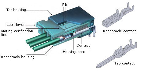
Figure 2: An example of wire connection
(Cross-sectional view of a connection made with a pressure welding technique)
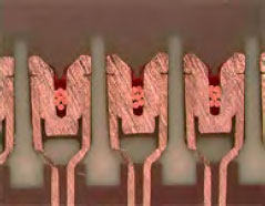
Pressure
Guidelines for Selecting the Right Connector
Are the number of wires and shape all that matter?
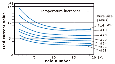
The number of connecting wires and the shape are indeed the first checkpoints when selecting the right connector. However, it is also important to consider the current and pressure in the circuit. As a matter of fact, the circuit current will determine the wire diameter, which in turn will determine the appropriate connector. There are several types of contacts available depending on the wire diameter. It is important for the contacts to match not only the diameter of the conductor, but also the diameter of the cover. In choosing the plating for a contact, it is necessary to know the magnitude of the current and pressure, as well as the environment in which the connector will be used. The specific current and pressure vary depending on the type of connector. As a rule of thumb, a highly reliable gold plating is used in low-current, low-pressure connectors, and a cost-effective tin plating is used in any other connectors. The number of poles is another topic that should be considered. Inserting and removing a connector will create unexpectedly high energy. This is because each of the contacts creates energy, and thus higher energy is created when there are more poles. It is possible to reduce contact pressure per contact with gold plating, but not with tin plating. Tin plating requires a relatively high contact pressure, which leads to a smaller maximum pole number compared to gold plating (Figure 3).
In other words, gold plating should be used with multi-polar connectors when the current is low. Note that a single connector cannot have both gold and tin plating; mixing tin and gold results in a high ionization tendency. Ionization can cause condensation, which in turn can easily cause corrosion. In order to avoid the accidental mixing of different metals, it is best to be consistent with the type of plating used within an application or set. It is also important to ensure that the mixing of substances does not occur in the process of building and maintaining equipment.
Figure 3: Types of plating and the corresponding maximum pole numbers

Preventing Human Error
Points to Consider when Designing a Connector
Connectors are easy to design because they are made to connect.
Although connectors are simple parts, but caution is still required when designing them. For example, de-rating is required when the current in the wires is high, because each of the wires individually contributes to temperature increase (Figure 4).
Figure 4: An example of de-rating in accordance with pole numbers
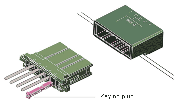
It is also important to design connectors in a way that prevents human error, as building a wire-to-board connector, in particular, requires the use of hands. One of the typical human errors is misinsertion; where the individual applies the connector in the wrong place or direction. It is not uncommon to mistake one connector for another or to forcefully insert a connector in the wrong direction without noticing the error. Therefore, many connectors are shaped asymmetrically so that they can only be inserted one way. This can prevent misinsertion, although it is more important to build a structure that can minimize human error. For example, one should avoid planning a design in which multiple connectors are connected to a single substrate, because this can lead to misinsertion. If several connectors of the same type must be used on a single substrate, they should be color-coded or given a keying plug, a device that prevents misinsertion (Figure 5). There are also connectors with a structure (keying) that prevents misinsertion in the housing.
Finally, lack of workspace planning is also a common error. This error is preventable by saving sufficient workspace during assembly and maintenance. It is necessary to provide clear boundaries on the work surface for different parts, including wire harnesses. Since workspace planning is related to board and structure design, making such mistakes can be easier than it seems.
Figure 5: Keying plug to prevent misinsertion
Avoiding Emergencies
Mounting and Handling
What should I pay attention to when mounting?
Firstly, for pressure bonding, it is crucial to use proper tools such as a proper applicator for the connectors and manually operated pressure-bonding tools. Swaging with pliers cannot guarantee perfect bonding. Similarly, it is crucial to use the designated “unplugging tool” to unplug contacts when changing wires for maintenance or fixing the wire orders to rectify a mistake made. Secondly, it is critical to insert the connector straight. Be careful not to insert a connector at an angle when working in a small area. It is also crucial to ensure that the pressure-bonded contacts are completely placed inside the housing. Remember that an incomplete connector mating cannot be detected immediately after application, but can cause problems later.
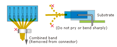
Avoid putting pressure on the housing or contacts when mounting. Bending a wire forcefully or combining the wires near the connector can have damaging results (Figure 6).
Figure 6: How to avoid damaging a connector
[PR]
-
Over 4100 new products from Tyco Electronics
Tyco Electronics’ product offer includes passive electronic components, such as connectors, relays, switches, circuit protection devices and much more.


RS e-newsletters gives u the latest scoop at your convenience.
